As every beginning CUDA programmer knows, the address spaces for the CPU and GPU are separate: the CPU cannot read or write the GPU’s device memory, and in turn, the GPU cannot read or write the CPU’s memory. As a result, the application must explicitly copy data to and from the GPU’s memory in order to process it.
The reality is a bit more complicated, and has gotten more so as CUDA added new capabilities such as mapped pinned memory and peer-to-peer access. This section gives a detailed description of how address spaces work in CUDA, starting from first principles.
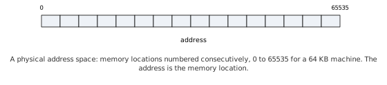
Virtual address spaces are such a pervasive and successful abstraction that most programmers use and benefit from them every day, without ever knowing that they exist. They are an extension of the original insight that it was useful to assign consecutive numbers to the memory locations in the computer. The standard unit of measure is the byte and e.g. a computer with 64K of memory had memory locations 0..65535. The 16-bit values used to read and write these memory locations were known as addresses8 and the reading, writing, and the general problem of computing addresses for memory was known as addressing.
Figure 2-17. Simple 16-bit Address Space.
Early computers performed physical addressing: they would compute a memory location and then read or write the corresponding memory location, as shown above. As software grew more complex and computers hosting multiple users or running multiple jobs grew more common, it became clear that allowing any program to read or write any physical memory location was unacceptable – software running on the machine could fatally corrupt other software by writing the wrong memory location. Besides the robustness concern, there were also security concerns: software could spy on other software by reading memory locations it did not “own.”
As a result, modern computers implement virtual address spaces: each program gets a view of memory similar to Figure 2-17, but each program gets its own address space. They cannot read or write memory belonging to other programs without special permission from the operating system. Instead of specifying a physical address, the machine instruction specifies a virtual address to be translated into a physical address by performing a series of lookups into tables that were set up by the operating system.
In most systems, the virtual address space is divided into pages, units of addressing that are at least 4096 bytes in size. Instead of referencing physical memory directly from the address, the hardware looks up a page table entry (PTE) that specifies the physical address where the page’s memory resides.
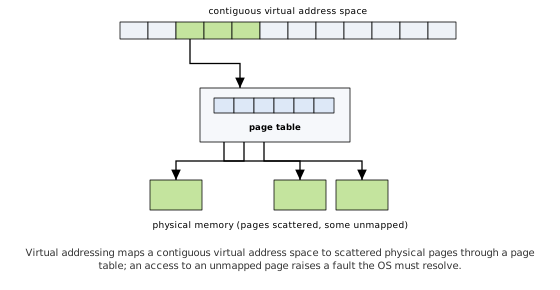
Figure 2-18. Virtual Address Space9
It should be clear from Figure 2-18 that virtual addressing enables a contiguous virtual address space to map to discontiguous pages in physical memory. Also, when an application attempts to read or write a memory location whose page has not been mapped to physical memory, the hardware signals a fault that must be handled by the operating system.
Besides a physical memory location, the PTEs contain permissions bits that the hardware can validate while doing the address translation. For example, the operating system can make pages read-only and the hardware will signal a fault if the application attempts to write the page.
Operating systems use virtual memory hardware to implement many features:
Lazy allocation: Large amounts of memory can be “allocated” by setting aside PTEs with no physical memory backing them – if the application that requested the memory happens to access one of those pages, the OS resolves the fault by finding a page of physical memory at that time.
Demand paging: Memory that has not been referenced in some time can be copied to disk, to increase the number of physical pages available for active processes, and the page marked nonresident. If the memory is referenced again, the hardware signals a page fault and the OS retrieves the page’s data and copies it to a physical page, fixing up the PTE to point there, before resuming execution.
Copy-on-write: Virtual memory can be “copied” by creating a second set of PTEs that map to the same physical pages, then marking both sets of PTEs read-only. If the hardware catches an attempt to write to one of those pages, the OS can copy it to another physical page, mark both PTEs writeable again, and resume execution. If the application only writes to a small percentage of pages that were “copied,” copy-on-write is a big performance win.
Mapped file I/O: Files can be mapped into the address space, and page faults can be resolved by accessing the file. For applications that perform random access on the file, it may be advantageous to delegate the memory management to the CPU cache hierarchy and the highly optimized VMM code in the operating system, especially since it is tightly coupled to the mass storage drivers.
It is important to understand that address translation is performed on every memory access performed by the CPU. To make this operation fast, the CPU contains a lot of special hardware – especially caches called translation lookaside buffers (TLBs) that hold recently-translated address ranges, and “page walkers,” special hardware that resolves cache misses in the TLBs by reading the page tables10. Modern CPUs also include hardware support for “unified address spaces,” where multiple CPUs can access each other’s memory efficiently via AMD’s HT (HyperTransport) and Intel’s QuickPath Interconnect (QPI). Since these hardware facilities enable CPUs to access any memory location in the system using a unified address space, this section refers to “the CPU” and the “CPU address space” regardless of how many CPUs are in the system.
On the GPU, CUDA also uses virtual address spaces, although the hardware does not support as rich a feature set as do the CPUs. GPUs do enforce memory protections, so CUDA programs cannot accidentally read or corrupt other CUDA programs’ memory, or access memory that hasn’t been mapped for them by the kernel mode driver. But for most of CUDA’s history, GPUs did not support demand paging, so every byte of virtual memory allocated by CUDA had to be backed by a byte of physical memory – a significant limitation, since demand paging is the underlying hardware mechanism used by operating systems to implement most of the features outlined above.
Hardware support for demand paging arrived with the Pascal
architecture (2016), whose Page Migration Engine enables the GPU to take
page faults and service them by migrating pages between system and
device memory; Volta (2017) added access counters, so that pages migrate
based on observed access patterns rather than on first touch. Demand
paging is the enabling technology for modern managed memory (described
in Section 5.7): allocations made with cudaMallocManaged() can exceed
the GPU’s physical memory, with pages migrating on demand to wherever
they are referenced. Memory allocated with cudaMalloc(), in contrast, is
physically backed for its entire lifetime.
Since each GPU has its own memory and address translation hardware, the CUDA address space is separate from the CPU address space where the host code in a CUDA application runs.
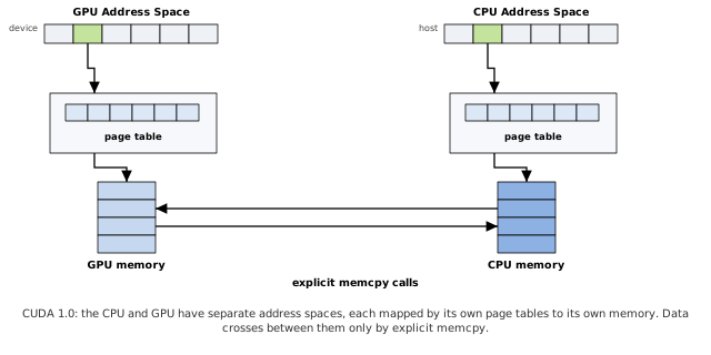
Figure 2-19. Disjoint Address Spaces
Figure 2-19 shows the address space architecture for CUDA as of version 1.0, before mapped pinned memory became available. The CPU and GPU each had their own address spaces, mapped with each device’s own page tables. The two devices exchanged data via explicit memcpy commands. The GPU could allocate pinned memory – page-locked memory that had been mapped for DMA by the GPU – but pinned memory only made DMA faster, it did not enable CUDA kernels to access host memory12.
The CUDA driver tracks pinned memory ranges, and automatically accelerates memcpy operations that reference them. Asynchronous memcpy calls require pinned memory ranges, to ensure that the operating system does not unmap or move the physical memory before the memcpy is performed.
Not all CUDA applications can allocate the host memory that they wish to process using CUDA – for example, a CUDA-aware plugin to a large, extensible application may want to operate on host memory that was allocated by non-CUDA-aware code. To accommodate that use case, CUDA provides the ability to register existing host address ranges, which page-locks a virtual address range, maps it for the GPU, and adds the address range to the tracking data structure so CUDA knows it is pinned. The memory then can be passed to asynchronous memcpy calls or otherwise treated as if it were allocated by CUDA.
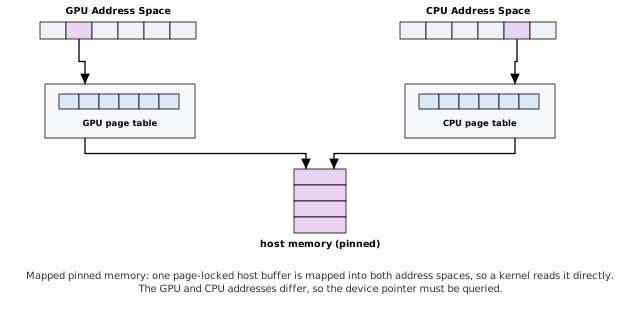
Figure 2-20. Mapped Pinned Memory
CUDA provides a feature called mapped pinned memory, shown
in Figure 2-20. Mapped pinned memory is page-locked host memory that has
been mapped into the CUDA address space, where CUDA kernels can read or
write it directly. The page tables of both the CPU and the GPU are
updated so that both the CPU and the GPU have address ranges that point
to the same host memory buffer. Since the address spaces are different,
the GPU pointer(s) to the buffer must be queried using
cuMemHostGetDevicePointer()/ cudaHostGetDevicePointer()13.
CUDA also provides a feature called portable pinned memory, shown in Figure 2-21. Making pinned memory ‘portable’ causes the CUDA driver to map it for all GPUs in the system, not just the one whose context is current. A separate set of page table entries is created for the CPU and for every GPU in the system, enabling the corresponding device to translate virtual addresses to the underlying physical memory. The host memory range also is added to every active CUDA context’s tracking mechanism, so every GPU will recognize the portable allocation as pinned.
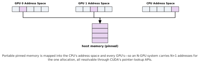
Figure 2-21. Portable, Mapped Pinned Memory
Figure 2-21 likely represents the limit of developer tolerance for multiple address spaces. Here, a 2-GPU system has 3 addresses for an allocation; a 4-GPU system would have 5 addresses. Although CUDA has fast APIs to look up a given CPU address range and pass back the corresponding GPU address range, having N+1 addresses on an N-GPU system, all for the same allocation, is inconvenient to say the least.
Multiple address spaces are required for 32-bit CUDA GPUs, which can only map 232=4GiB of address space; since some high-end GPUs have up to 4GiB of device memory, they are hard-pressed to address all of device memory and also map any pinned memory, let alone use the same address space as the CPU.
But on 64-bit platforms with Fermi GPUs, a simpler abstraction is possible.
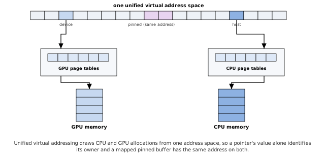
Figure 2-22. Unified Virtual Addressing (UVA)
CUDA provides a feature called unified virtual addressing (UVA), shown in Figure 2-22. When UVA is in force, CUDA allocates memory for both CPUs and GPUs from the same virtual address space. The CUDA driver accomplishes this by having its initialization routine perform large virtual allocations from the CPU address space – allocations that are not backed by physical memory – then mapping GPU allocations into those address ranges. Since x64 CPUs support 48-bit virtual address spaces14, while CUDA GPUs only support 40 bits, applications using UVA should make sure CUDA gets initialized early, to guard against CPU code using virtual address space in the lower 40 bits.
For mapped pinned allocations, the GPU and CPU pointers are the same.
For other types of allocation, CUDA can infer the device for which a
given allocation was performed from the address. As a result, the family
of linear memcpy functions (cudaMemcpy() with a direction specified,
cuMemcpyHtoD(), cuMemcpyDtoH(), etc.) have been replaced by simplified
cuMemcpy() and cudaMemcpy() functions that do not take a memory
direction.
UVA is enabled automatically on UVA-capable systems. At the time of
this writing, UVA is enabled on 64-bit Linux and 64-bit Windows when
using the TCC driver; the WDDM driver does not yet support UVA. To query
whether UVA is in effect, check
cudaDeviceProp::unifiedAddressing or call
cuDeviceGetAttribute() with
CU_DEVICE_ATTRIBUTE_UNIFIED_ADDRESSING. When UVA is in
effect, all pinned allocations performed by CUDA are both mapped and
portable. Note that for system memory that has been pinned using
cuMemRegisterHost(), the device pointers still must be queried using
cu(da)HostGetDevicePointer().
Even when UVA is in effect, the CPU(s) cannot access device memory. In addition, by default, the GPU(s) cannot access one another’s memory.
In the final stage of our journey through CUDA’s virtual memory
abstractions, we discuss peer-to-peer mapping of device memory, shown in
Figure 2-23. Peer-to-peer enables a GPU to read or write memory that
resides in another GPU. Peer-to-peer mapping is supported only on
UVA-enabled platforms, and only works on GPUs that are connected to the
same I/O hub. Because UVA is always in force when using peer-to-peer,
the address ranges for different devices do not overlap and the driver
(and runtime) can infer the owning device from a pointer value.
cuPointerGetAttribute() or cudaPointerGetAttributes() may be used to
query the attributes of a pointer. The structure passed back by
cudaPointerGetAttributes() is as follows:
    struct cudaPointerAttributes {
        enum cudaMemoryType memoryType;
        int device;
        void *devicePointer;
        void *hostPointer;
    }
memoryType may be cudaMemoryTypeHost or
cudaMemoryTypeDevice.
device is the device for which the pointer was
allocated. For device memory, device identifies the
device where the memory corresponding to ptr
was allocated. For host memory, device identifies the
device that was current when the allocation was performed.
devicePointer gives the device pointer value that may be
used to reference ptr from the current device. If
ptr cannot be accessed by the current device,
devicePointer is NULL.
hostPointer gives the host pointer value that may be
used to reference ptr from the CPU. If ptr
cannot be accessed by the current host, hostPointer is
NULL.
Peer-to-peer memory addressing may be asymmetric; note that Figure 2-23 shows an asymmetric mapping in which GPU 1’s allocations are visible to GPU 0, but not vice versa. In order for GPUs to see each other’s memory, each GPU must explicitly map the other’s memory.
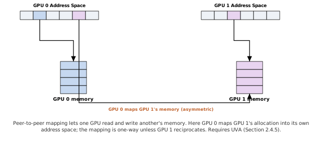
Figure 2-23. Peer-to-peer
Like PO boxes… computer scientists love their metaphors.↩︎
In practice, no hardware implements a single-level page table as shown here. At minimum, the address is split into at least 2 indices: an index into a “page directory” of page tables, and an index into the page table selected by the first index. The hierarchical design reduces the amount of memory needed for the page tables and enables inactive page tables to be marked nonresident and swapped to disk, much like inactive pages.↩︎
It is possible to write programs (for both CPUs and CUDA) that expose the size and structure of the TLBs and/or the memory overhead of the page walkers, if they stride through enough memory in a short-enough period of time.↩︎
The x86-specific terms for kernel mode and user mode are “Ring 0” and “Ring 3,” respectively.↩︎
All Tesla-class GPUs, and Fermi GPUs on 32-bit platforms, can map pinned memory for memcpy in a 40-bit address space that is outside the CUDA address space used by kernels.↩︎
For multi-GPU configurations, CUDA also provides a
feature called ‘portable’ pinned memory that causes the allocation to be
mapped into every GPU’s address space. The GPUs may not all be
the same, so there’s no guarantee that cu(da)HostGetDevicePointer() will
return the same value for different GPUs!↩︎
as of the time of this writing. 48 bits of virtual address space=256 terabytes!↩︎